
Advanced Switching and Magnetic Sensing Solutions
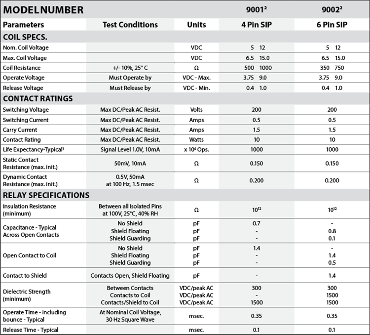
The SIP relay is the industry standard when high reliability and consistent performance are desired in a compact package. The 9001 and 9002 are high performance relays ideally suited for Automatic Test Equipment, Instrumentation, RF and Telecommunications applications. The specification tables allow you to select the appropriate relay for your application. Download Datasheet

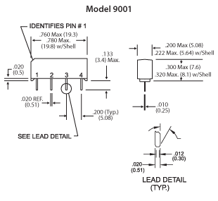
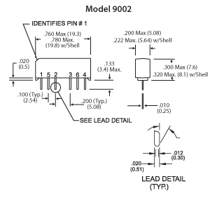
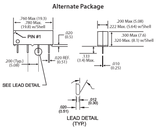
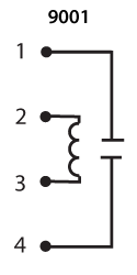
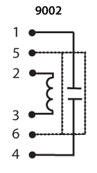
Top View:
Dot stamped on relay refers to pin #1
Grid = .1”x.1” (2.54mm x 2.54mm)
1Consult factory for life expectancy at other switching loads. Resistance >0.5Ω defines end of life or failure to open.
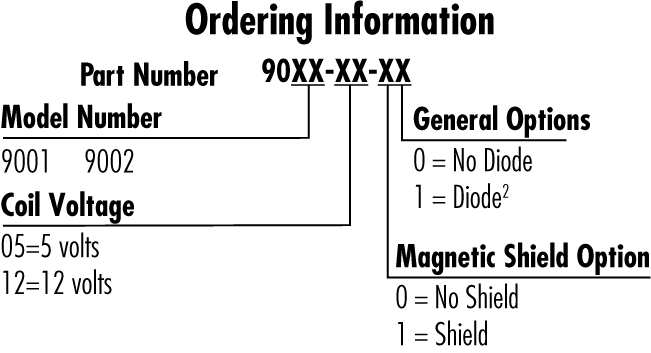
2Optional diode is connected to pin #2(+) and pin #3(-). Correct coil polarity must be observed.
Storage Temp: -35°C to +100°C; Operating Temp: -20°C to +85°C; Solder Temp: 270°C max; 10 sec. max
All electrical parameters measured at 25°C unless otherwise specified.
Vibration: 20 G’s to 2000 Hz; Shock: 50 G’s
For RF Graph Performance, see “RF Graphs” section of the “Reed Relay Technical & Application Information”