Advanced Switching and Magnetic Sensing Solutions
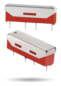
Molded SIP relays are the industry standard when high reliability and consistent performance are desired in a compact package. The 9104 Series adds high voltage switching capability and high voltage standoff capability to a SIP relay package. These high voltage, high performance relays are ideally suited for Automatic Test Equipment, Instrumentation, Battery Management, Solar and Process Control applications where voltage isolation is a key design requirement. Download Datasheet
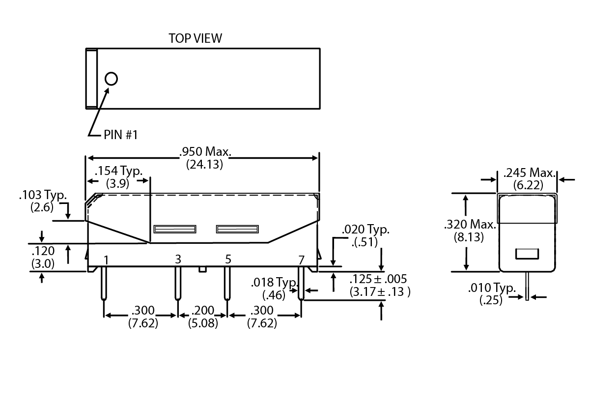
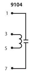
Top View:
Dot stamped on top of relay refers to pin #1 location
Grid = .1”x.1” (2.54mm x 2.54mm)
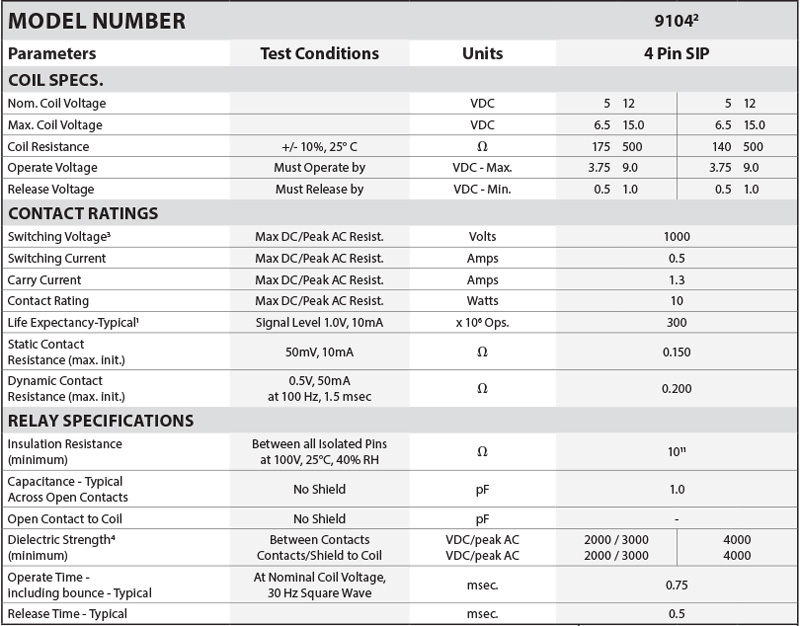
1Consult factory for life expectancy at other switching loads.
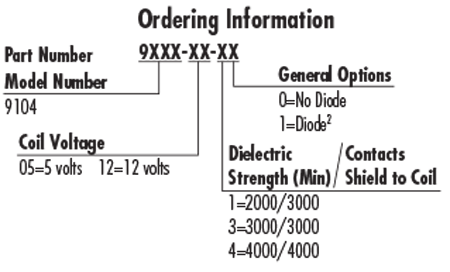
2Optional diode is connected to pin #3(+) and pin #5(-). Correct coil polarity must be observed.
3Switch current limited to 1.0mA @ 1000V.
4
Storage Temp: -35°C to +100°C; Operating Temp: -20°C to +85°C; Solder Temp: 270°C max; 10 sec. max
All electrical parameters measured at 25°C unless otherwise specified.
Vibration: 20 G’s to 2000 Hz; Shock: 50 G’s