Advanced Switching and Magnetic Sensing Solutions
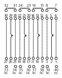
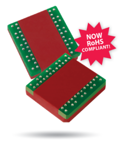
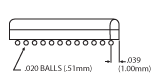
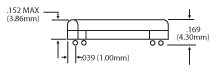
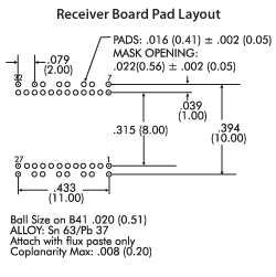
The B41 contains four independent form A channels in one planar quad package. Coto’s Ball Grid Array (BGA) construction offers a breakthrough in reed relay performance. This patented technology1 allows for shorter RF paths in a controlled 50 Ω environment to minimize signal attentuation. The designer is now able to switch or pass signals with wider bandwidth and faster rise time than alternative technologies. This is particularly important in Mixed Signal IC testers. This four-in-one BGA packaging allows relays to be integrated easily on boards designed for surface mount processing. Download Datasheet
1Protected by one or more of the following US Patents: 6025768, 6052045, 6294971, 6683518, RE38381 and other foreign patents.
Storage Temp: -35°C to +100°C; Operating Temp: -20°C to +85°C.
Moisture Sensitivity Level: Handle as J-STD-020B Level 5A. (This may be relaxed with B41ROHS, but only after qualification testing is complete.)
Consult the Coto Technology website (cotorelay.com) for recommended reflow profile for SnPb Eutectic and SAC Alloys.
Vibration Exposure: Sinusoidal vibration with an amplitude of 10g over a 10Hz to 2000Hz frequency range shall not cause damage to relay.

For RF Graph Performance, see “RF Graphs” section of the “Reed Relay Technical & Application Information”