Advanced Switching and Magnetic Sensing Solutions
 Coto Classic™ REED RELAYS
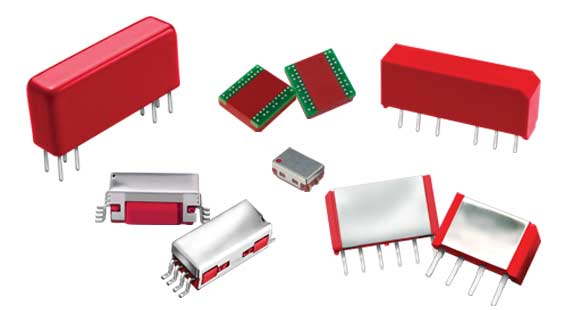
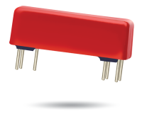
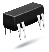
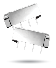
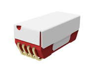
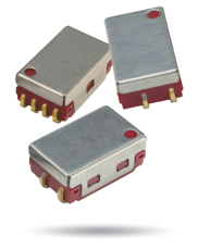
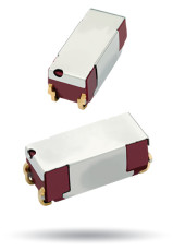
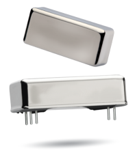
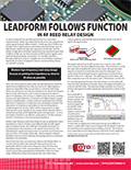
The Coto Classic™ Reed Relays Product Line is composed of a wide range of relay types for a multitude of applications. Non-standard package sizes and pinouts, custom coil and shielding designs, and multi-pole configurations are common variables.
Coto relays can switch from small signals to high-power/high voltage loads, carrying up to 5 amps, can provide switching currents up to 3 amps, switching voltages up to 7.5KV, breaking voltages up to 13KV, and dielectric strength above 20KV. Coto relays are qualified to the highest electrical test specifications in the reed relay industry. All of our relays are 100% tested.
Download the CotoClassic Reed Relays Selector Chart| Part Number | Package | Contact Form | Switching Voltage | Breakdown Voltage | Switch Power (V/A) | Switching Current | ES Shield | RF Coax Shield |
|---|---|---|---|---|---|---|---|---|
| 2200-2302 | PICO | 1A | 150 | 250 | 10 | 0.50 | No | Yes |
| 2204-05-401 | PICO | 1A | 200 | 250 | 10 | 0.50 | No | No |
| 2204-05-411 | PICO | 1A | 200 | 250 | 10 | 0.50 | Yes | No |
| 2204-05-421 | PICO | 1A | 200 | 250 | 10 | 0.50 | No | Yes |
| 2204-12-301 | PICO | 1A | 200 | 250 | 10 | 0.50 | No | No |
| 2204-12-311 | PICO | 1A | 200 | 250 | 10 | 0.50 | Yes | No |
| 2204-12-321 | PICO | 1A | 200 | 250 | 10 | 0.50 | No | Yes |
| 2211-05-301 | PICO | 1C | 100 | 200 | 3 | 0.25 | No | No |
| 2211-12-301 | PICO | 1C | 100 | 200 | 3 | 0.25 | No | No |
| 2332-05-000 | PICO | 2A | 200 | 250 | 10 | 0.50 | No | No |
| 2332-05-010 | PICO | 2A | 200 | 250 | 10 | 0.50 | Yes | No |
| 2332-05-020 | PICO | 2A | 200 | 250 | 10 | 0.50 | No | Yes |
| 2332-12-000 | PICO | 2A | 200 | 250 | 10 | 0.50 | No | No |
| 2332-12-010 | PICO | 2A | 200 | 250 | 10 | 0.50 | Yes | No |
| 2332-12-020 | PICO | 2A | 200 | 250 | 10 | 0.50 | No | Yes |
| 2333-05-000 | PICO | 3A | 200 | 250 | 10 | 0.50 | No | No |
| 2333-12-000 | PICO | 3A | 200 | 250 | 10 | 0.50 | No | No |
| 2341-05-000 | PICO | 1C | 200 | 250 | 10 | 0.50 | No | No |
| 2341-05-010 | PICO | 1C | 200 | 250 | 10 | 0.50 | Yes | No |
| 2341-05-020 | PICO | 1C | 200 | 250 | 10 | 0.50 | No | Yes |
| 2341-12-000 | PICO | 1C | 200 | 250 | 10 | 0.50 | No | No |
| 2341-12-010 | PICO | 1C | 200 | 250 | 10 | 0.50 | Yes | No |
| 2341-12-020 | PICO | 1C | 200 | 250 | 10 | 0.50 | No | Yes |
| 2342-05-000 | PICO | 2C | 100 | 200 | 3 | 0.25 | No | No |
| 2342-12-000 | PICO | 2C | 100 | 200 | 3 | 0.25 | No | No |
| 2362-05-000 | PICO | 2C | 100 | 200 | 3 | 0.25 | N/A | N/A |
| 2362-12-000 | PICO | 2C | 100 | 200 | 3 | 0.25 | N/A | N/A |
| 2904-05-401 | PICO | 1A | 200 | 350 | 10 | 0.50 | No | No |
| 2904-05-411 | PICO | 1A | 200 | 350 | 10 | 0.50 | Yes | No |
| 2904-05-421 | PICO | 1A | 200 | 350 | 10 | 0.50 | No | Yes |
| 2904-12-301 | PICO | 1A | 200 | 350 | 10 | 0.50 | No | No |
| 2904-12-311 | PICO | 1A | 200 | 350 | 10 | 0.50 | Yes | No |
| 2904-12-321 | PICO | 1A | 200 | 350 | 10 | 0.50 | No | Yes |
| 2911-05-301 | PICO | 1C | 150 | 200 | 3 | 0.25 | No | No |
| 2911-05-311 | PICO | 1C | 150 | 200 | 3 | 0.25 | Yes | No |
| 2911-05-321 | PICO | 1C | 150 | 200 | 3 | 0.25 | No | Yes |
| 2911-12-301 | PICO | 1C | 150 | 200 | 3 | 0.25 | No | No |
| 2911-12-311 | PICO | 1C | 150 | 200 | 3 | 0.25 | Yes | No |
| 2911-12-321 | PICO | 1C | 150 | 200 | 3 | 0.25 | No | Yes |
| 2920-05-101 | PICO | 1A | 500 | 1,000 | 50 | 1.00 | No | No |
| 2920-05-111 | PICO | 1A | 500 | 1,000 | 50 | 1.00 | Yes | No |
| 2920-05-121 | PICO | 1A | 500 | 1,000 | 50 | 1.00 | No | Yes |
| 2920-12-101 | PICO | 1A | 500 | 1,000 | 50 | 1.00 | No | No |
| 2920-12-111 | PICO | 1A | 500 | 1,000 | 50 | 1.00 | Yes | No |
| 2920-12-121 | PICO | 1A | 500 | 1,000 | 50 | 1.00 | No | Yes |
| 3501-05-510 | Potted | 1A | 200 | 700 | 10 | 0.50 | No | N/A |
| 3501-05-511 | Potted | 1A | 200 | 700 | 10 | 0.50 | Yes | N/A |
| 3501-05-710 | Potted | 1A | 200 | 700 | 10 | 0.50 | No | N/A |
| 3501-05-711 | Potted | 1A | 200 | 700 | 10 | 0.50 | Yes | N/A |
| 3501-05-810 | Potted | 1A | 200 | 700 | 10 | 0.50 | No | N/A |
| 3501-05-811 | Potted | 1A | 200 | 700 | 10 | 0.50 | Yes | N/A |
| 3501-05-910 | Potted | 1A | 200 | 700 | 10 | 0.50 | No | N/A |
| 3501-05-911 | Potted | 1A | 200 | 700 | 10 | 0.50 | Yes | N/A |
| 3501-12-510 | Potted | 1A | 200 | 700 | 10 | 0.50 | No | N/A |
| 3501-12-511 | Potted | 1A | 200 | 700 | 10 | 0.50 | Yes | N/A |
| 3501-12-710 | Potted | 1A | 200 | 700 | 10 | 0.50 | No | N/A |
| 3501-12-711 | Potted | 1A | 200 | 700 | 10 | 0.50 | Yes | N/A |
| 3501-12-810 | Potted | 1A | 200 | 700 | 10 | 0.50 | No | N/A |
| 3501-12-811 | Potted | 1A | 200 | 700 | 10 | 0.50 | Yes | N/A |
| 3501-12-910 | Potted | 1A | 200 | 700 | 10 | 0.50 | No | N/A |
| 3501-12-911 | Potted | 1A | 200 | 700 | 10 | 0.50 | Yes | N/A |
| 3502-05-510 | Potted | 2A | 200 | 350 | 10 | 0.50 | No | N/A |
| 3502-05-511 | Potted | 2A | 200 | 350 | 10 | 0.50 | Yes | N/A |
| 3502-05-710 | Potted | 2A | 200 | 350 | 10 | 0.50 | No | N/A |
| 3502-05-711 | Potted | 2A | 200 | 350 | 10 | 0.50 | Yes | N/A |
| 3502-05-810 | Potted | 2A | 200 | 350 | 10 | 0.50 | No | N/A |
| 3502-05-811 | Potted | 2A | 200 | 350 | 10 | 0.50 | Yes | N/A |
| 3502-05-910 | Potted | 2A | 200 | 350 | 10 | 0.50 | No | N/A |
| 3502-05-911 | Potted | 2A | 200 | 350 | 10 | 0.50 | Yes | N/A |
| 3502-12-510 | Potted | 2A | 200 | 350 | 10 | 0.50 | No | N/A |
| 3502-12-511 | Potted | 2A | 200 | 350 | 10 | 0.50 | Yes | N/A |
| 3502-12-710 | Potted | 2A | 200 | 350 | 10 | 0.50 | No | N/A |
| 3502-12-711 | Potted | 2A | 200 | 350 | 10 | 0.50 | Yes | N/A |
| 3502-12-810 | Potted | 2A | 200 | 350 | 10 | 0.50 | No | N/A |
| 3502-12-811 | Potted | 2A | 200 | 350 | 10 | 0.50 | Yes | N/A |
| 3502-12-910 | Potted | 2A | 200 | 350 | 10 | 0.50 | No | N/A |
| 3502-12-911 | Potted | 2A | 200 | 350 | 10 | 0.50 | Yes | N/A |
| 3520-05-110 | Potted | 2A | 500 | 1,000 | 28 | 1.00 | No | N/A |
| 3520-05-111 | Potted | 2A | 500 | 1,000 | 28 | 1.00 | Yes | N/A |
| 3520-05-910 | Potted | 2A | 500 | 1,000 | 28 | 1.00 | No | N/A |
| 3520-05-911 | Potted | 2A | 500 | 1,000 | 28 | 1.00 | Yes | N/A |
| 3520-12-110 | Potted | 2A | 500 | 1,000 | 28 | 1.00 | No | N/A |
| 3520-12-111 | Potted | 2A | 500 | 1,000 | 28 | 1.00 | Yes | N/A |
| 3520-12-910 | Potted | 2A | 500 | 1,000 | 28 | 1.00 | No | N/A |
| 3520-12-911 | Potted | 2A | 500 | 1,000 | 28 | 1.00 | Yes | N/A |
| 3540-05-810 | Potted | 1A | 500 | 1,500 | 10 | 0.50 | No | N/A |
| 3540-05-811 | Potted | 1A | 500 | 1,500 | 10 | 0.50 | Yes | N/A |
| 3540-05-910 | Potted | 1A | 500 | 1,500 | 10 | 0.50 | No | N/A |
| 3540-05-911 | Potted | 1A | 500 | 1,500 | 10 | 0.50 | Yes | N/A |
| 3540-12-810 | Potted | 1A | 500 | 1,500 | 10 | 0.50 | No | N/A |
| 3540-12-811 | Potted | 1A | 500 | 1,500 | 10 | 0.50 | Yes | N/A |
| 3540-12-910 | Potted | 1A | 500 | 1,500 | 10 | 0.50 | No | N/A |
| 3540-12-911 | Potted | 1A | 500 | 1,500 | 10 | 0.50 | Yes | N/A |
| 3541-05-810 | Potted | 2A | 500 | 1,500 | 10 | 0.50 | No | N/A |
| 3541-05-811 | Potted | 2A | 500 | 1,500 | 10 | 0.50 | Yes | N/A |
| 3541-05-910 | Potted | 2A | 500 | 1,500 | 10 | 0.50 | No | N/A |
| 3541-05-911 | Potted | 2A | 500 | 1,500 | 10 | 0.50 | Yes | N/A |
| 3541-12-810 | Potted | 2A | 500 | 1,500 | 10 | 0.50 | No | N/A |
| 3541-12-811 | Potted | 2A | 500 | 1,500 | 10 | 0.50 | Yes | N/A |
| 3541-12-910 | Potted | 2A | 500 | 1,500 | 10 | 0.50 | No | N/A |
| 3541-12-911 | Potted | 2A | 500 | 1,500 | 10 | 0.50 | Yes | N/A |
| 3602-05-52 | Potted | 2A | 150 | 250 | 5 | 0.25 | Yes | N/A |
| 3602-05-72 | Potted | 2A | 150 | 250 | 5 | 0.25 | Yes | N/A |
| 3602-05-82 | Potted | 2A | 150 | 250 | 5 | 0.25 | Yes | N/A |
| 3602-05-92 | Potted | 2A | 150 | 250 | 5 | 0.25 | Yes | N/A |
| 3602-12-52 | Potted | 2A | 150 | 250 | 5 | 0.25 | Yes | N/A |
| 3602-12-72 | Potted | 2A | 150 | 250 | 5 | 0.25 | Yes | N/A |
| 3602-12-82 | Potted | 2A | 150 | 250 | 5 | 0.25 | Yes | N/A |
| 3602-12-92 | Potted | 2A | 150 | 250 | 5 | 0.25 | Yes | N/A |
| 3650-05-52 | Potted | 3A | 150 | 250 | 5 | 0.25 | Yes | N/A |
| 3650-05-72 | Potted | 3A | 150 | 250 | 5 | 0.25 | Yes | N/A |
| 3650-05-82 | Potted | 3A | 150 | 250 | 5 | 0.25 | Yes | N/A |
| 3650-05-92 | Potted | 3A | 150 | 250 | 5 | 0.25 | Yes | N/A |
| 3650-12-52 | Potted | 3A | 150 | 250 | 5 | 0.25 | Yes | N/A |
| 3650-12-72 | Potted | 3A | 150 | 250 | 5 | 0.25 | Yes | N/A |
| 3650-12-82 | Potted | 3A | 150 | 250 | 5 | 0.25 | Yes | N/A |
| 3650-12-92 | Potted | 3A | 150 | 250 | 5 | 0.25 | Yes | N/A |
| 3660-05-52 | Potted | 3A | 150 | 250 | 5 | 0.25 | Yes | N/A |
| 3660-05-72 | Potted | 3A | 150 | 250 | 5 | 0.25 | Yes | N/A |
| 3660-05-82 | Potted | 3A | 150 | 250 | 5 | 0.25 | Yes | N/A |
| 3660-05-92 | Potted | 3A | 150 | 250 | 5 | 0.25 | Yes | N/A |
| 3660-12-52 | Potted | 3A | 150 | 250 | 5 | 0.25 | Yes | N/A |
| 3660-12-72 | Potted | 3A | 150 | 250 | 5 | 0.25 | Yes | N/A |
| 3660-12-82 | Potted | 3A | 150 | 250 | 5 | 0.25 | Yes | N/A |
| 3660-12-92 | Potted | 3A | 150 | 250 | 5 | 0.25 | Yes | N/A |
| 5501-05-1 | Potted | 1A | 7,500 | 10,000 | 50 | 3.00 | N/A | N/A |
| 5501-12-1 | Potted | 1A | 7,500 | 10,000 | 50 | 3.00 | N/A | N/A |
| 5501-24-1 | Potted | 1A | 7,500 | 10,000 | 50 | 3.00 | N/A | N/A |
| 5502-05-1 | Potted | 1B | 7,500 | 10,000 | 50 | 3.00 | N/A | N/A |
| 5502-12-1 | Potted | 1B | 7,500 | 10,000 | 50 | 3.00 | N/A | N/A |
| 5502-24-1 | Potted | 1B | 7,500 | 10,000 | 50 | 3.00 | N/A | N/A |
| 5503-05-1 | Potted | 1A | 3,500 | 7,500 | 200 | 3.00 | N/A | N/A |
| 5503-12-1 | Potted | 1A | 3,500 | 7,500 | 200 | 3.00 | N/A | N/A |
| 5503-24-1 | Potted | 1A | 3,500 | 7,500 | 200 | 3.00 | N/A | N/A |
| 5504-05-1 | Potted | 1B | 3,500 | 7,500 | 200 | 3.00 | N/A | N/A |
| 5504-12-1 | Potted | 1B | 3,500 | 7,500 | 200 | 3.00 | N/A | N/A |
| 5504-24-1 | Potted | 1B | 3,500 | 7,500 | 200 | 3.00 | N/A | N/A |
| 7003-5193 | Potted | 1A | 50 | 200 | 3 | 0.05 | N/A | N/A |
| 7101-05-1000 | Potted | 1A | 200 | 250 | 10 | 0.50 | No | N/A |
| 7101-05-1001 | Potted | 1A | 200 | 250 | 10 | 0.50 | No | N/A |
| 7101-05-1010 | Potted | 1A | 200 | 250 | 10 | 0.50 | Yes | N/A |
| 7101-05-1011 | Potted | 1A | 200 | 250 | 10 | 0.50 | Yes | N/A |
| 7101-05-1100 | Potted | 1A | 200 | 250 | 10 | 0.50 | No | N/A |
| 7101-05-1101 | Potted | 1A | 200 | 250 | 10 | 0.50 | No | N/A |
| 7101-05-1110 | Potted | 1A | 200 | 250 | 10 | 0.50 | Yes | N/A |
| 7101-05-1111 | Potted | 1A | 200 | 250 | 10 | 0.50 | Yes | N/A |
| 7101-12-1000 | Potted | 1A | 200 | 250 | 10 | 0.50 | No | N/A |
| 7101-12-1001 | Potted | 1A | 200 | 250 | 10 | 0.50 | No | N/A |
| 7101-12-1010 | Potted | 1A | 200 | 250 | 10 | 0.50 | Yes | N/A |
| 7101-12-1011 | Potted | 1A | 200 | 250 | 10 | 0.50 | Yes | N/A |
| 7101-12-1100 | Potted | 1A | 200 | 250 | 10 | 0.50 | No | N/A |
| 7101-12-1101 | Potted | 1A | 200 | 250 | 10 | 0.50 | No | N/A |
| 7101-12-1110 | Potted | 1A | 200 | 250 | 10 | 0.50 | Yes | N/A |
| 7101-12-1111 | Potted | 1A | 200 | 250 | 10 | 0.50 | Yes | N/A |
| 7101-24-1000 | Potted | 1A | 200 | 250 | 10 | 0.50 | No | N/A |
| 7101-24-1001 | Potted | 1A | 200 | 250 | 10 | 0.50 | No | N/A |
| 7101-24-1010 | Potted | 1A | 200 | 250 | 10 | 0.50 | Yes | N/A |
| 7101-24-1011 | Potted | 1A | 200 | 250 | 10 | 0.50 | Yes | N/A |
| 7101-24-1100 | Potted | 1A | 200 | 250 | 10 | 0.50 | No | N/A |
| 7101-24-1101 | Potted | 1A | 200 | 250 | 10 | 0.50 | No | N/A |
| 7101-24-1110 | Potted | 1A | 200 | 250 | 10 | 0.50 | Yes | N/A |
| 7101-24-1111 | Potted | 1A | 200 | 250 | 10 | 0.50 | Yes | N/A |
| 7102-05-1000 | Potted | 2A | 200 | 250 | 10 | 0.50 | No | N/A |
| 7102-05-1001 | Potted | 2A | 200 | 250 | 10 | 0.50 | No | N/A |
| 7102-05-1100 | Potted | 2A | 200 | 250 | 10 | 0.50 | No | N/A |
| 7102-05-1101 | Potted | 2A | 200 | 250 | 10 | 0.50 | No | N/A |
| 7102-05-1110 | Potted | 2A | 200 | 250 | 10 | 0.50 | Yes | N/A |
| 7102-05-1111 | Potted | 2A | 200 | 250 | 10 | 0.50 | Yes | N/A |
| 7102-12-1000 | Potted | 2A | 200 | 250 | 10 | 0.50 | No | N/A |
| 7102-12-1001 | Potted | 2A | 200 | 250 | 10 | 0.50 | No | N/A |
| 7102-12-1100 | Potted | 2A | 200 | 250 | 10 | 0.50 | No | N/A |
| 7102-12-1101 | Potted | 2A | 200 | 250 | 10 | 0.50 | No | N/A |
| 7102-12-1110 | Potted | 2A | 200 | 250 | 10 | 0.50 | Yes | N/A |
| 7102-12-1111 | Potted | 2A | 200 | 250 | 10 | 0.50 | Yes | N/A |
| 7102-24-1000 | Potted | 2A | 200 | 250 | 10 | 0.50 | No | N/A |
| 7102-24-1001 | Potted | 2A | 200 | 250 | 10 | 0.50 | No | N/A |
| 7102-24-1100 | Potted | 2A | 200 | 250 | 10 | 0.50 | No | N/A |
| 7102-24-1101 | Potted | 2A | 200 | 250 | 10 | 0.50 | No | N/A |
| 7102-24-1110 | Potted | 2A | 200 | 250 | 10 | 0.50 | Yes | N/A |
| 7102-24-1111 | Potted | 2A | 200 | 250 | 10 | 0.50 | Yes | N/A |
| 7103-05-1000 | Potted | 3A | 200 | 250 | 10 | 0.50 | No | N/A |
| 7103-05-1001 | Potted | 3A | 200 | 250 | 10 | 0.50 | No | N/A |
| 7103-05-1010 | Potted | 3A | 200 | 250 | 10 | 0.50 | Yes | N/A |
| 7103-05-1011 | Potted | 3A | 200 | 250 | 10 | 0.50 | Yes | N/A |
| 7103-05-1100 | Potted | 3A | 200 | 250 | 10 | 0.50 | No | N/A |
| 7103-05-1101 | Potted | 3A | 200 | 250 | 10 | 0.50 | No | N/A |
| 7103-05-1110 | Potted | 3A | 200 | 250 | 10 | 0.50 | Yes | N/A |
| 7103-05-1111 | Potted | 3A | 200 | 250 | 10 | 0.50 | Yes | N/A |
| 7103-12-1000 | Potted | 3A | 200 | 250 | 10 | 0.50 | No | N/A |
| 7103-12-1001 | Potted | 3A | 200 | 250 | 10 | 0.50 | No | N/A |
| 7103-12-1010 | Potted | 3A | 200 | 250 | 10 | 0.50 | Yes | N/A |
| 7103-12-1011 | Potted | 3A | 200 | 250 | 10 | 0.50 | Yes | N/A |
| 7103-12-1100 | Potted | 3A | 200 | 250 | 10 | 0.50 | No | N/A |
| 7103-12-1101 | Potted | 3A | 200 | 250 | 10 | 0.50 | No | N/A |
| 7103-12-1110 | Potted | 3A | 200 | 250 | 10 | 0.50 | Yes | N/A |
| 7103-12-1111 | Potted | 3A | 200 | 250 | 10 | 0.50 | Yes | N/A |
| 7103-24-1000 | Potted | 3A | 200 | 250 | 10 | 0.50 | No | N/A |
| 7103-24-1001 | Potted | 3A | 200 | 250 | 10 | 0.50 | No | N/A |
| 7103-24-1010 | Potted | 3A | 200 | 250 | 10 | 0.50 | Yes | N/A |
| 7103-24-1011 | Potted | 3A | 200 | 250 | 10 | 0.50 | Yes | N/A |
| 7103-24-1100 | Potted | 3A | 200 | 250 | 10 | 0.50 | No | N/A |
| 7103-24-1101 | Potted | 3A | 200 | 250 | 10 | 0.50 | No | N/A |
| 7103-24-1110 | Potted | 3A | 200 | 250 | 10 | 0.50 | Yes | N/A |
| 7103-24-1111 | Potted | 3A | 200 | 250 | 10 | 0.50 | Yes | N/A |
| 7104-05-1000 | Potted | 4A | 200 | 250 | 10 | 0.50 | No | N/A |
| 7104-05-1001 | Potted | 4A | 200 | 250 | 10 | 0.50 | No | N/A |
| 7104-05-1010 | Potted | 4A | 200 | 250 | 10 | 0.50 | Yes | N/A |
| 7104-05-1011 | Potted | 4A | 200 | 250 | 10 | 0.50 | Yes | N/A |
| 7104-05-1100 | Potted | 4A | 200 | 250 | 10 | 0.50 | No | N/A |
| 7104-05-1101 | Potted | 4A | 200 | 250 | 10 | 0.50 | No | N/A |
| 7104-05-1110 | Potted | 4A | 200 | 250 | 10 | 0.50 | Yes | N/A |
| 7104-05-1111 | Potted | 4A | 200 | 250 | 10 | 0.50 | Yes | N/A |
| 7104-12-1000 | Potted | 4A | 200 | 250 | 10 | 0.50 | No | N/A |
| 7104-12-1001 | Potted | 4A | 200 | 250 | 10 | 0.50 | No | N/A |
| 7104-12-1010 | Potted | 4A | 200 | 250 | 10 | 0.50 | Yes | N/A |
| 7104-12-1011 | Potted | 4A | 200 | 250 | 10 | 0.50 | Yes | N/A |
| 7104-12-1100 | Potted | 4A | 200 | 250 | 10 | 0.50 | No | N/A |
| 7104-12-1101 | Potted | 4A | 200 | 250 | 10 | 0.50 | No | N/A |
| 7104-12-1110 | Potted | 4A | 200 | 250 | 10 | 0.50 | Yes | N/A |
| 7104-12-1111 | Potted | 4A | 200 | 250 | 10 | 0.50 | Yes | N/A |
| 7104-24-1000 | Potted | 4A | 200 | 250 | 10 | 0.50 | No | N/A |
| 7104-24-1001 | Potted | 4A | 200 | 250 | 10 | 0.50 | No | N/A |
| 7104-24-1010 | Potted | 4A | 200 | 250 | 10 | 0.50 | Yes | N/A |
| 7104-24-1011 | Potted | 4A | 200 | 250 | 10 | 0.50 | Yes | N/A |
| 7104-24-1100 | Potted | 4A | 200 | 250 | 10 | 0.50 | No | N/A |
| 7104-24-1101 | Potted | 4A | 200 | 250 | 10 | 0.50 | No | N/A |
| 7104-24-1110 | Potted | 4A | 200 | 250 | 10 | 0.50 | Yes | N/A |
| 7104-24-1111 | Potted | 4A | 200 | 250 | 10 | 0.50 | Yes | N/A |
| 7121-05-1000 | Potted | 1B | 200 | 250 | 10 | 0.50 | No | N/A |
| 7121-05-1001 | Potted | 1B | 200 | 250 | 10 | 0.50 | No | N/A |
| 7121-05-1010 | Potted | 1B | 200 | 250 | 10 | 0.50 | Yes | N/A |
| 7121-05-1011 | Potted | 1B | 200 | 250 | 10 | 0.50 | Yes | N/A |
| 7121-05-1100 | Potted | 1B | 200 | 250 | 10 | 0.50 | No | N/A |
| 7121-05-1101 | Potted | 1B | 200 | 250 | 10 | 0.50 | No | N/A |
| 7121-05-1110 | Potted | 1B | 200 | 250 | 10 | 0.50 | Yes | N/A |
| 7121-05-1111 | Potted | 1B | 200 | 250 | 10 | 0.50 | Yes | N/A |
| 7121-12-1000 | Potted | 1B | 200 | 250 | 10 | 0.50 | No | N/A |
| 7121-12-1001 | Potted | 1B | 200 | 250 | 10 | 0.50 | No | N/A |
| 7121-12-1010 | Potted | 1B | 200 | 250 | 10 | 0.50 | Yes | N/A |
| 7121-12-1011 | Potted | 1B | 200 | 250 | 10 | 0.50 | Yes | N/A |
| 7121-12-1100 | Potted | 1B | 200 | 250 | 10 | 0.50 | No | N/A |
| 7121-12-1101 | Potted | 1B | 200 | 250 | 10 | 0.50 | No | N/A |
| 7121-12-1110 | Potted | 1B | 200 | 250 | 10 | 0.50 | Yes | N/A |
| 7121-12-1111 | Potted | 1B | 200 | 250 | 10 | 0.50 | Yes | N/A |
| 7121-24-1000 | Potted | 1B | 200 | 250 | 10 | 0.50 | No | N/A |
| 7121-24-1001 | Potted | 1B | 200 | 250 | 10 | 0.50 | No | N/A |
| 7121-24-1010 | Potted | 1B | 200 | 250 | 10 | 0.50 | Yes | N/A |
| 7121-24-1011 | Potted | 1B | 200 | 250 | 10 | 0.50 | Yes | N/A |
| 7121-24-1100 | Potted | 1B | 200 | 250 | 10 | 0.50 | No | N/A |
| 7121-24-1101 | Potted | 1B | 200 | 250 | 10 | 0.50 | No | N/A |
| 7121-24-1110 | Potted | 1B | 200 | 250 | 10 | 0.50 | Yes | N/A |
| 7121-24-1111 | Potted | 1B | 200 | 250 | 10 | 0.50 | Yes | N/A |
| 7122-05-1000 | Potted | 2B | 200 | 250 | 10 | 0.50 | No | N/A |
| 7122-05-1001 | Potted | 2B | 200 | 250 | 10 | 0.50 | No | N/A |
| 7122-05-1010 | Potted | 2B | 200 | 250 | 10 | 0.50 | Yes | N/A |
| 7122-05-1011 | Potted | 2B | 200 | 250 | 10 | 0.50 | Yes | N/A |
| 7122-05-1100 | Potted | 2B | 200 | 250 | 10 | 0.50 | No | N/A |
| 7122-05-1101 | Potted | 2B | 200 | 250 | 10 | 0.50 | No | N/A |
| 7122-05-1110 | Potted | 2B | 200 | 250 | 10 | 0.50 | Yes | N/A |
| 7122-05-1111 | Potted | 2B | 200 | 250 | 10 | 0.50 | Yes | N/A |
| 7122-12-1000 | Potted | 2B | 200 | 250 | 10 | 0.50 | No | N/A |
| 7122-12-1001 | Potted | 2B | 200 | 250 | 10 | 0.50 | No | N/A |
| 7122-12-1010 | Potted | 2B | 200 | 250 | 10 | 0.50 | Yes | N/A |
| 7122-12-1011 | Potted | 2B | 200 | 250 | 10 | 0.50 | Yes | N/A |
| 7122-12-1100 | Potted | 2B | 200 | 250 | 10 | 0.50 | No | N/A |
| 7122-12-1101 | Potted | 2B | 200 | 250 | 10 | 0.50 | No | N/A |
| 7122-12-1110 | Potted | 2B | 200 | 250 | 10 | 0.50 | Yes | N/A |
| 7122-12-1111 | Potted | 2B | 200 | 250 | 10 | 0.50 | Yes | N/A |
| 7122-24-1000 | Potted | 2B | 200 | 250 | 10 | 0.50 | No | N/A |
| 7122-24-1001 | Potted | 2B | 200 | 250 | 10 | 0.50 | No | N/A |
| 7122-24-1010 | Potted | 2B | 200 | 250 | 10 | 0.50 | Yes | N/A |
| 7122-24-1011 | Potted | 2B | 200 | 250 | 10 | 0.50 | Yes | N/A |
| 7122-24-1100 | Potted | 2B | 200 | 250 | 10 | 0.50 | No | N/A |
| 7122-24-1101 | Potted | 2B | 200 | 250 | 10 | 0.50 | No | N/A |
| 7122-24-1110 | Potted | 2B | 200 | 250 | 10 | 0.50 | Yes | N/A |
| 7122-24-1111 | Potted | 2B | 200 | 250 | 10 | 0.50 | Yes | N/A |
| 7141-05-1000 | Potted | 1C | 150 | 200 | 10 | 0.25 | No | N/A |
| 7141-05-1001 | Potted | 1C | 150 | 200 | 10 | 0.25 | No | N/A |
| 7141-05-1010 | Potted | 1C | 150 | 200 | 10 | 0.25 | Yes | N/A |
| 7141-05-1011 | Potted | 1C | 150 | 200 | 10 | 0.25 | Yes | N/A |
| 7141-05-1100 | Potted | 1C | 150 | 200 | 10 | 0.25 | No | N/A |
| 7141-05-1101 | Potted | 1C | 150 | 200 | 10 | 0.25 | No | N/A |
| 7141-05-1110 | Potted | 1C | 150 | 200 | 10 | 0.25 | Yes | N/A |
| 7141-05-1111 | Potted | 1C | 150 | 200 | 10 | 0.25 | Yes | N/A |
| 7141-12-1000 | Potted | 1C | 150 | 200 | 10 | 0.25 | No | N/A |
| 7141-12-1001 | Potted | 1C | 150 | 200 | 10 | 0.25 | No | N/A |
| 7141-12-1010 | Potted | 1C | 150 | 200 | 10 | 0.25 | Yes | N/A |
| 7141-12-1011 | Potted | 1C | 150 | 200 | 10 | 0.25 | Yes | N/A |
| 7141-12-1100 | Potted | 1C | 150 | 200 | 10 | 0.25 | No | N/A |
| 7141-12-1101 | Potted | 1C | 150 | 200 | 10 | 0.25 | No | N/A |
| 7141-12-1110 | Potted | 1C | 150 | 200 | 10 | 0.25 | Yes | N/A |
| 7141-12-1111 | Potted | 1C | 150 | 200 | 10 | 0.25 | Yes | N/A |
| 7141-24-1000 | Potted | 1C | 150 | 200 | 10 | 0.25 | No | N/A |
| 7141-24-1001 | Potted | 1C | 150 | 200 | 10 | 0.25 | No | N/A |
| 7141-24-1010 | Potted | 1C | 150 | 200 | 10 | 0.25 | Yes | N/A |
| 7141-24-1011 | Potted | 1C | 150 | 200 | 10 | 0.25 | Yes | N/A |
| 7141-24-1100 | Potted | 1C | 150 | 200 | 10 | 0.25 | No | N/A |
| 7141-24-1101 | Potted | 1C | 150 | 200 | 10 | 0.25 | No | N/A |
| 7141-24-1110 | Potted | 1C | 150 | 200 | 10 | 0.25 | Yes | N/A |
| 7141-24-1111 | Potted | 1C | 150 | 200 | 10 | 0.25 | Yes | N/A |
| 7142-05-1000 | Potted | 2C | 150 | 200 | 10 | 0.25 | No | N/A |
| 7142-05-1001 | Potted | 2C | 150 | 200 | 10 | 0.25 | No | N/A |
| 7142-05-1010 | Potted | 2C | 150 | 200 | 10 | 0.25 | Yes | N/A |
| 7142-05-1011 | Potted | 2C | 150 | 200 | 10 | 0.25 | Yes | N/A |
| 7142-05-1100 | Potted | 2C | 150 | 200 | 10 | 0.25 | No | N/A |
| 7142-05-1101 | Potted | 2C | 150 | 200 | 10 | 0.25 | No | N/A |
| 7142-05-1110 | Potted | 2C | 150 | 200 | 10 | 0.25 | Yes | N/A |
| 7142-05-1111 | Potted | 2C | 150 | 200 | 10 | 0.25 | Yes | N/A |
| 7142-12-1000 | Potted | 2C | 150 | 200 | 10 | 0.25 | No | N/A |
| 7142-12-1001 | Potted | 2C | 150 | 200 | 10 | 0.25 | No | N/A |
| 7142-12-1010 | Potted | 2C | 150 | 200 | 10 | 0.25 | Yes | N/A |
| 7142-12-1011 | Potted | 2C | 150 | 200 | 10 | 0.25 | Yes | N/A |
| 7142-12-1100 | Potted | 2C | 150 | 200 | 10 | 0.25 | No | N/A |
| 7142-12-1101 | Potted | 2C | 150 | 200 | 10 | 0.25 | No | N/A |
| 7142-12-1110 | Potted | 2C | 150 | 200 | 10 | 0.25 | Yes | N/A |
| 7142-12-1111 | Potted | 2C | 150 | 200 | 10 | 0.25 | Yes | N/A |
| 7142-24-1000 | Potted | 2C | 150 | 200 | 10 | 0.25 | No | N/A |
| 7142-24-1001 | Potted | 2C | 150 | 200 | 10 | 0.25 | No | N/A |
| 7142-24-1010 | Potted | 2C | 150 | 200 | 10 | 0.25 | Yes | N/A |
| 7142-24-1011 | Potted | 2C | 150 | 200 | 10 | 0.25 | Yes | N/A |
| 7142-24-1100 | Potted | 2C | 150 | 200 | 10 | 0.25 | No | N/A |
| 7142-24-1101 | Potted | 2C | 150 | 200 | 10 | 0.25 | No | N/A |
| 7142-24-1110 | Potted | 2C | 150 | 200 | 10 | 0.25 | Yes | N/A |
| 7142-24-1111 | Potted | 2C | 150 | 200 | 10 | 0.25 | Yes | N/A |
| 7143-05-1000 | Potted | 3C | 150 | 200 | 10 | 0.25 | No | N/A |
| 7143-05-1001 | Potted | 3C | 150 | 200 | 10 | 0.25 | No | N/A |
| 7143-05-1010 | Potted | 3C | 150 | 200 | 10 | 0.25 | Yes | N/A |
| 7143-05-1011 | Potted | 3C | 150 | 200 | 10 | 0.25 | Yes | N/A |
| 7143-05-1100 | Potted | 3C | 150 | 200 | 10 | 0.25 | No | N/A |
| 7143-05-1101 | Potted | 3C | 150 | 200 | 10 | 0.25 | No | N/A |
| 7143-05-1110 | Potted | 3C | 150 | 200 | 10 | 0.25 | Yes | N/A |
| 7143-05-1111 | Potted | 3C | 150 | 200 | 10 | 0.25 | Yes | N/A |
| 7143-12-1000 | Potted | 3C | 150 | 200 | 10 | 0.25 | No | N/A |
| 7143-12-1001 | Potted | 3C | 150 | 200 | 10 | 0.25 | No | N/A |
| 7143-12-1010 | Potted | 3C | 150 | 200 | 10 | 0.25 | Yes | N/A |
| 7143-12-1011 | Potted | 3C | 150 | 200 | 10 | 0.25 | Yes | N/A |
| 7143-12-1100 | Potted | 3C | 150 | 200 | 10 | 0.25 | No | N/A |
| 7143-12-1101 | Potted | 3C | 150 | 200 | 10 | 0.25 | No | N/A |
| 7143-12-1110 | Potted | 3C | 150 | 200 | 10 | 0.25 | Yes | N/A |
| 7143-12-1111 | Potted | 3C | 150 | 200 | 10 | 0.25 | Yes | N/A |
| 7143-24-1000 | Potted | 3C | 150 | 200 | 10 | 0.25 | No | N/A |
| 7143-24-1001 | Potted | 3C | 150 | 200 | 10 | 0.25 | No | N/A |
| 7143-24-1010 | Potted | 3C | 150 | 200 | 10 | 0.25 | Yes | N/A |
| 7143-24-1011 | Potted | 3C | 150 | 200 | 10 | 0.25 | Yes | N/A |
| 7143-24-1100 | Potted | 3C | 150 | 200 | 10 | 0.25 | No | N/A |
| 7143-24-1101 | Potted | 3C | 150 | 200 | 10 | 0.25 | No | N/A |
| 7143-24-1110 | Potted | 3C | 150 | 200 | 10 | 0.25 | Yes | N/A |
| 7143-24-1111 | Potted | 3C | 150 | 200 | 10 | 0.25 | Yes | N/A |
| 7150-05-1000 | Potted | 1A | 200 | 250 | 10 | 0.50 | No | N/A |
| 7150-05-1001 | Potted | 1A | 200 | 250 | 10 | 0.50 | No | N/A |
| 7150-05-1010 | Potted | 1A | 200 | 250 | 10 | 0.50 | Yes | N/A |
| 7150-05-1011 | Potted | 1A | 200 | 250 | 10 | 0.50 | Yes | N/A |
| 7150-05-1100 | Potted | 1A | 200 | 250 | 10 | 0.50 | No | N/A |
| 7150-05-1101 | Potted | 1A | 200 | 250 | 10 | 0.50 | No | N/A |
| 7150-05-1110 | Potted | 1A | 200 | 250 | 10 | 0.50 | Yes | N/A |
| 7150-05-1111 | Potted | 1A | 200 | 250 | 10 | 0.50 | Yes | N/A |
| 7150-12-1000 | Potted | 1A | 200 | 250 | 10 | 0.50 | No | N/A |
| 7150-12-1001 | Potted | 1A | 200 | 250 | 10 | 0.50 | No | N/A |
| 7150-12-1010 | Potted | 1A | 200 | 250 | 10 | 0.50 | Yes | N/A |
| 7150-12-1011 | Potted | 1A | 200 | 250 | 10 | 0.50 | Yes | N/A |
| 7150-12-1100 | Potted | 1A | 200 | 250 | 10 | 0.50 | No | N/A |
| 7150-12-1101 | Potted | 1A | 200 | 250 | 10 | 0.50 | No | N/A |
| 7150-12-1110 | Potted | 1A | 200 | 250 | 10 | 0.50 | Yes | N/A |
| 7150-12-1111 | Potted | 1A | 200 | 250 | 10 | 0.50 | Yes | N/A |
| 7160-05-1000 | Potted | 1A1B | 200 | 250 | 10 | 0.50 | No | N/A |
| 7160-05-1001 | Potted | 1A1B | 200 | 250 | 10 | 0.50 | No | N/A |
| 7160-05-1010 | Potted | 1A1B | 200 | 250 | 10 | 0.50 | Yes | N/A |
| 7160-05-1011 | Potted | 1A1B | 200 | 250 | 10 | 0.50 | Yes | N/A |
| 7160-05-1100 | Potted | 1A1B | 200 | 250 | 10 | 0.50 | No | N/A |
| 7160-05-1101 | Potted | 1A1B | 200 | 250 | 10 | 0.50 | No | N/A |
| 7160-05-1110 | Potted | 1A1B | 200 | 250 | 10 | 0.50 | Yes | N/A |
| 7160-05-1111 | Potted | 1A1B | 200 | 250 | 10 | 0.50 | Yes | N/A |
| 7160-12-1000 | Potted | 1A1B | 200 | 250 | 10 | 0.50 | No | N/A |
| 7160-12-1001 | Potted | 1A1B | 200 | 250 | 10 | 0.50 | No | N/A |
| 7160-12-1010 | Potted | 1A1B | 200 | 250 | 10 | 0.50 | Yes | N/A |
| 7160-12-1011 | Potted | 1A1B | 200 | 250 | 10 | 0.50 | Yes | N/A |
| 7160-12-1100 | Potted | 1A1B | 200 | 250 | 10 | 0.50 | No | N/A |
| 7160-12-1101 | Potted | 1A1B | 200 | 250 | 10 | 0.50 | No | N/A |
| 7160-12-1110 | Potted | 1A1B | 200 | 250 | 10 | 0.50 | Yes | N/A |
| 7160-12-1111 | Potted | 1A1B | 200 | 250 | 10 | 0.50 | Yes | N/A |
| 7160-24-1000 | Potted | 1A1B | 200 | 250 | 10 | 0.50 | No | N/A |
| 7160-24-1001 | Potted | 1A1B | 200 | 250 | 10 | 0.50 | No | N/A |
| 7160-24-1010 | Potted | 1A1B | 200 | 250 | 10 | 0.50 | Yes | N/A |
| 7160-24-1011 | Potted | 1A1B | 200 | 250 | 10 | 0.50 | Yes | N/A |
| 7160-24-1100 | Potted | 1A1B | 200 | 250 | 10 | 0.50 | No | N/A |
| 7160-24-1101 | Potted | 1A1B | 200 | 250 | 10 | 0.50 | No | N/A |
| 7160-24-1110 | Potted | 1A1B | 200 | 250 | 10 | 0.50 | Yes | N/A |
| 7160-24-1111 | Potted | 1A1B | 200 | 250 | 10 | 0.50 | Yes | N/A |
| 7201-05-1000 | Potted | 1A | 500 | 250 | 50 | 1.00 | No | N/A |
| 7201-05-1001 | Potted | 1A | 500 | 250 | 50 | 1.00 | No | N/A |
| 7201-05-1010 | Potted | 1A | 500 | 250 | 50 | 1.00 | Yes | N/A |
| 7201-05-1011 | Potted | 1A | 500 | 250 | 50 | 1.00 | Yes | N/A |
| 7201-05-1100 | Potted | 1A | 500 | 250 | 50 | 1.00 | No | N/A |
| 7201-05-1101 | Potted | 1A | 500 | 250 | 50 | 1.00 | No | N/A |
| 7201-05-1110 | Potted | 1A | 500 | 250 | 50 | 1.00 | Yes | N/A |
| 7201-05-1111 | Potted | 1A | 500 | 250 | 50 | 1.00 | Yes | N/A |
| 7201-12-1000 | Potted | 1A | 500 | 1,000 | 50 | 1.00 | No | N/A |
| 7201-12-1001 | Potted | 1A | 500 | 1,000 | 50 | 1.00 | No | N/A |
| 7201-12-1010 | Potted | 1A | 500 | 1,000 | 50 | 1.00 | Yes | N/A |
| 7201-12-1011 | Potted | 1A | 500 | 1,000 | 50 | 1.00 | Yes | N/A |
| 7201-12-1100 | Potted | 1A | 500 | 1,000 | 50 | 1.00 | No | N/A |
| 7201-12-1101 | Potted | 1A | 500 | 1,000 | 50 | 1.00 | No | N/A |
| 7201-12-1110 | Potted | 1A | 500 | 1,000 | 50 | 1.00 | Yes | N/A |
| 7201-12-1111 | Potted | 1A | 500 | 1,000 | 50 | 1.00 | Yes | N/A |
| 7201-24-1000 | Potted | 1A | 500 | 1,000 | 50 | 1.00 | No | N/A |
| 7201-24-1001 | Potted | 1A | 500 | 1,000 | 50 | 1.00 | No | N/A |
| 7201-24-1010 | Potted | 1A | 500 | 1,000 | 50 | 1.00 | Yes | N/A |
| 7201-24-1011 | Potted | 1A | 500 | 1,000 | 50 | 1.00 | Yes | N/A |
| 7201-24-1100 | Potted | 1A | 500 | 1,000 | 50 | 1.00 | No | N/A |
| 7201-24-1101 | Potted | 1A | 500 | 1,000 | 50 | 1.00 | No | N/A |
| 7201-24-1110 | Potted | 1A | 500 | 1,000 | 50 | 1.00 | Yes | N/A |
| 7201-24-1111 | Potted | 1A | 500 | 1,000 | 50 | 1.00 | Yes | N/A |
| 7202-05-1000 | Potted | 2A | 500 | 1,000 | 50 | 1.00 | No | N/A |
| 7202-05-1001 | Potted | 2A | 500 | 1,000 | 50 | 1.00 | No | N/A |
| 7202-05-1010 | Potted | 2A | 500 | 1,000 | 50 | 1.00 | Yes | N/A |
| 7202-05-1011 | Potted | 2A | 500 | 1,000 | 50 | 1.00 | Yes | N/A |
| 7202-05-1100 | Potted | 2A | 500 | 1,000 | 50 | 1.00 | No | N/A |
| 7202-05-1101 | Potted | 2A | 500 | 1,000 | 50 | 1.00 | No | N/A |
| 7202-05-1110 | Potted | 2A | 500 | 1,000 | 50 | 1.00 | Yes | N/A |
| 7202-05-1111 | Potted | 2A | 500 | 1,000 | 50 | 1.00 | Yes | N/A |
| 7202-12-1000 | Potted | 2A | 500 | 1,000 | 50 | 1.00 | No | N/A |
| 7202-12-1001 | Potted | 2A | 500 | 1,000 | 50 | 1.00 | No | N/A |
| 7202-12-1010 | Potted | 2A | 500 | 1,000 | 50 | 1.00 | Yes | N/A |
| 7202-12-1011 | Potted | 2A | 500 | 1,000 | 50 | 1.00 | Yes | N/A |
| 7202-12-1100 | Potted | 2A | 500 | 1,000 | 50 | 1.00 | No | N/A |
| 7202-12-1101 | Potted | 2A | 500 | 1,000 | 50 | 1.00 | No | N/A |
| 7202-12-1110 | Potted | 2A | 500 | 1,000 | 50 | 1.00 | Yes | N/A |
| 7202-12-1111 | Potted | 2A | 500 | 1,000 | 50 | 1.00 | Yes | N/A |
| 7202-24-1000 | Potted | 2A | 500 | 1,000 | 50 | 1.00 | No | N/A |
| 7202-24-1001 | Potted | 2A | 500 | 1,000 | 50 | 1.00 | No | N/A |
| 7202-24-1010 | Potted | 2A | 500 | 1,000 | 50 | 1.00 | Yes | N/A |
| 7202-24-1011 | Potted | 2A | 500 | 1,000 | 50 | 1.00 | Yes | N/A |
| 7202-24-1100 | Potted | 2A | 500 | 1,000 | 50 | 1.00 | No | N/A |
| 7202-24-1101 | Potted | 2A | 500 | 1,000 | 50 | 1.00 | No | N/A |
| 7202-24-1110 | Potted | 2A | 500 | 1,000 | 50 | 1.00 | Yes | N/A |
| 7202-24-1111 | Potted | 2A | 500 | 1,000 | 50 | 1.00 | Yes | N/A |
| 7203-05-1000 | Potted | 3A | 500 | 1,000 | 50 | 1.00 | No | N/A |
| 7203-05-1001 | Potted | 3A | 500 | 1,000 | 50 | 1.00 | No | N/A |
| 7203-05-1010 | Potted | 3A | 500 | 1,000 | 50 | 1.00 | Yes | N/A |
| 7203-05-1011 | Potted | 3A | 500 | 1,000 | 50 | 1.00 | Yes | N/A |
| 7203-05-1100 | Potted | 3A | 500 | 1,000 | 50 | 1.00 | No | N/A |
| 7203-05-1101 | Potted | 3A | 500 | 1,000 | 50 | 1.00 | No | N/A |
| 7203-05-1110 | Potted | 3A | 500 | 1,000 | 50 | 1.00 | Yes | N/A |
| 7203-05-1111 | Potted | 3A | 500 | 1,000 | 50 | 1.00 | Yes | N/A |
| 7203-12-1000 | Potted | 3A | 500 | 1,000 | 50 | 1.00 | No | N/A |
| 7203-12-1001 | Potted | 3A | 500 | 1,000 | 50 | 1.00 | No | N/A |
| 7203-12-1010 | Potted | 3A | 500 | 1,000 | 50 | 1.00 | Yes | N/A |
| 7203-12-1011 | Potted | 3A | 500 | 1,000 | 50 | 1.00 | Yes | N/A |
| 7203-12-1100 | Potted | 3A | 500 | 1,000 | 50 | 1.00 | No | N/A |
| 7203-12-1101 | Potted | 3A | 500 | 1,000 | 50 | 1.00 | No | N/A |
| 7203-12-1110 | Potted | 3A | 500 | 1,000 | 50 | 1.00 | Yes | N/A |
| 7203-12-1111 | Potted | 3A | 500 | 1,000 | 50 | 1.00 | Yes | N/A |
| 7203-24-1000 | Potted | 3A | 500 | 1,000 | 50 | 1.00 | No | N/A |
| 7203-24-1001 | Potted | 3A | 500 | 1,000 | 50 | 1.00 | No | N/A |
| 7203-24-1010 | Potted | 3A | 500 | 1,000 | 50 | 1.00 | Yes | N/A |
| 7203-24-1011 | Potted | 3A | 500 | 1,000 | 50 | 1.00 | Yes | N/A |
| 7203-24-1100 | Potted | 3A | 500 | 1,000 | 50 | 1.00 | No | N/A |
| 7203-24-1101 | Potted | 3A | 500 | 1,000 | 50 | 1.00 | No | N/A |
| 7203-24-1110 | Potted | 3A | 500 | 1,000 | 50 | 1.00 | Yes | N/A |
| 7203-24-1111 | Potted | 3A | 500 | 1,000 | 50 | 1.00 | Yes | N/A |
| 7204-05-1000 | Potted | 4A | 500 | 1,000 | 50 | 1.00 | No | N/A |
| 7204-05-1001 | Potted | 4A | 500 | 1,000 | 50 | 1.00 | No | N/A |
| 7204-05-1010 | Potted | 4A | 500 | 1,000 | 50 | 1.00 | Yes | N/A |
| 7204-05-1011 | Potted | 4A | 500 | 1,000 | 50 | 1.00 | Yes | N/A |
| 7204-05-1100 | Potted | 4A | 500 | 1,000 | 50 | 1.00 | No | N/A |
| 7204-05-1101 | Potted | 4A | 500 | 1,000 | 50 | 1.00 | No | N/A |
| 7204-05-1110 | Potted | 4A | 500 | 1,000 | 50 | 1.00 | Yes | N/A |
| 7204-05-1111 | Potted | 4A | 500 | 1,000 | 50 | 1.00 | Yes | N/A |
| 7204-12-1000 | Potted | 4A | 500 | 1,000 | 50 | 1.00 | No | N/A |
| 7204-12-1001 | Potted | 4A | 500 | 1,000 | 50 | 1.00 | No | N/A |
| 7204-12-1010 | Potted | 4A | 500 | 1,000 | 50 | 1.00 | Yes | N/A |
| 7204-12-1011 | Potted | 4A | 500 | 1,000 | 50 | 1.00 | Yes | N/A |
| 7204-12-1100 | Potted | 4A | 500 | 1,000 | 50 | 1.00 | No | N/A |
| 7204-12-1101 | Potted | 4A | 500 | 1,000 | 50 | 1.00 | No | N/A |
| 7204-12-1110 | Potted | 4A | 500 | 1,000 | 50 | 1.00 | Yes | N/A |
| 7204-12-1111 | Potted | 4A | 500 | 1,000 | 50 | 1.00 | Yes | N/A |
| 7204-24-1000 | Potted | 4A | 500 | 1,000 | 50 | 1.00 | No | N/A |
| 7204-24-1001 | Potted | 4A | 500 | 1,000 | 50 | 1.00 | No | N/A |
| 7204-24-1010 | Potted | 4A | 500 | 1,000 | 50 | 1.00 | Yes | N/A |
| 7204-24-1011 | Potted | 4A | 500 | 1,000 | 50 | 1.00 | Yes | N/A |
| 7204-24-1100 | Potted | 4A | 500 | 1,000 | 50 | 1.00 | No | N/A |
| 7204-24-1101 | Potted | 4A | 500 | 1,000 | 50 | 1.00 | No | N/A |
| 7204-24-1110 | Potted | 4A | 500 | 1,000 | 50 | 1.00 | Yes | N/A |
| 7204-24-1111 | Potted | 4A | 500 | 1,000 | 50 | 1.00 | Yes | N/A |
| 7241-05-1000 | Potted | 1C | 500 | 1,000 | 50 | 1.00 | No | N/A |
| 7241-05-1001 | Potted | 1C | 500 | 1,000 | 50 | 1.00 | No | N/A |
| 7241-05-1010 | Potted | 1C | 500 | 1,000 | 50 | 1.00 | Yes | N/A |
| 7241-05-1011 | Potted | 1C | 500 | 1,000 | 50 | 1.00 | Yes | N/A |
| 7241-12-1000 | Potted | 1C | 500 | 1,000 | 50 | 1.00 | No | N/A |
| 7241-12-1001 | Potted | 1C | 500 | 1,000 | 50 | 1.00 | No | N/A |
| 7241-12-1010 | Potted | 1C | 500 | 1,000 | 50 | 1.00 | Yes | N/A |
| 7241-12-1011 | Potted | 1C | 500 | 1,000 | 50 | 1.00 | Yes | N/A |
| 7241-24-1000 | Potted | 1C | 500 | 1,000 | 50 | 1.00 | No | N/A |
| 7241-24-1001 | Potted | 1C | 500 | 1,000 | 50 | 1.00 | No | N/A |
| 7241-24-1010 | Potted | 1C | 500 | 1,000 | 50 | 1.00 | Yes | N/A |
| 7241-24-1011 | Potted | 1C | 500 | 1,000 | 50 | 1.00 | Yes | N/A |
| 7301-05-1000 | Potted | 1A | 500 | 1,200 | 10 | 0.50 | No | N/A |
| 7301-05-1001 | Potted | 1A | 500 | 1,200 | 10 | 0.50 | No | N/A |
| 7301-05-1010 | Potted | 1A | 500 | 1,200 | 10 | 0.50 | Yes | N/A |
| 7301-05-1011 | Potted | 1A | 500 | 1,200 | 10 | 0.50 | Yes | N/A |
| 7301-05-1100 | Potted | 1A | 500 | 1,200 | 10 | 0.50 | No | N/A |
| 7301-05-1101 | Potted | 1A | 500 | 1,200 | 10 | 0.50 | No | N/A |
| 7301-05-1110 | Potted | 1A | 500 | 1,200 | 10 | 0.50 | Yes | N/A |
| 7301-05-1111 | Potted | 1A | 500 | 1,200 | 10 | 0.50 | Yes | N/A |
| 7301-12-1000 | Potted | 1A | 500 | 1,200 | 10 | 0.50 | No | N/A |
| 7301-12-1001 | Potted | 1A | 500 | 1,200 | 10 | 0.50 | No | N/A |
| 7301-12-1010 | Potted | 1A | 500 | 1,200 | 10 | 0.50 | Yes | N/A |
| 7301-12-1011 | Potted | 1A | 500 | 1,200 | 10 | 0.50 | Yes | N/A |
| 7301-12-1100 | Potted | 1A | 500 | 1,200 | 10 | 0.50 | No | N/A |
| 7301-12-1101 | Potted | 1A | 500 | 1,200 | 10 | 0.50 | No | N/A |
| 7301-12-1110 | Potted | 1A | 500 | 1,200 | 10 | 0.50 | Yes | N/A |
| 7301-12-1111 | Potted | 1A | 500 | 1,200 | 10 | 0.50 | Yes | N/A |
| 7301-24-1000 | Potted | 1A | 500 | 1,200 | 10 | 0.50 | No | N/A |
| 7301-24-1001 | Potted | 1A | 500 | 1,200 | 10 | 0.50 | No | N/A |
| 7301-24-1010 | Potted | 1A | 500 | 1,200 | 10 | 0.50 | Yes | N/A |
| 7301-24-1011 | Potted | 1A | 500 | 1,200 | 10 | 0.50 | Yes | N/A |
| 7301-24-1100 | Potted | 1A | 500 | 1,200 | 10 | 0.50 | No | N/A |
| 7301-24-1101 | Potted | 1A | 500 | 1,200 | 10 | 0.50 | No | N/A |
| 7301-24-1110 | Potted | 1A | 500 | 1,200 | 10 | 0.50 | Yes | N/A |
| 7301-24-1111 | Potted | 1A | 500 | 1,200 | 10 | 0.50 | Yes | N/A |
| 7302-05-1000 | Potted | 2A | 500 | 1,200 | 10 | 0.50 | No | N/A |
| 7302-05-1001 | Potted | 2A | 500 | 1,200 | 10 | 0.50 | No | N/A |
| 7302-05-1010 | Potted | 2A | 500 | 1,200 | 10 | 0.50 | Yes | N/A |
| 7302-05-1011 | Potted | 2A | 500 | 1,200 | 10 | 0.50 | Yes | N/A |
| 7302-05-1100 | Potted | 2A | 500 | 1,200 | 10 | 0.50 | No | N/A |
| 7302-05-1101 | Potted | 2A | 500 | 1,200 | 10 | 0.50 | No | N/A |
| 7302-05-1110 | Potted | 2A | 500 | 1,200 | 10 | 0.50 | Yes | N/A |
| 7302-05-1111 | Potted | 2A | 500 | 1,200 | 10 | 0.50 | Yes | N/A |
| 7302-12-1000 | Potted | 2A | 500 | 1,200 | 10 | 0.50 | No | N/A |
| 7302-12-1001 | Potted | 2A | 500 | 1,200 | 10 | 0.50 | No | N/A |
| 7302-12-1010 | Potted | 2A | 500 | 1,200 | 10 | 0.50 | Yes | N/A |
| 7302-12-1011 | Potted | 2A | 500 | 1,200 | 10 | 0.50 | Yes | N/A |
| 7302-12-1100 | Potted | 2A | 500 | 1,200 | 10 | 0.50 | No | N/A |
| 7302-12-1101 | Potted | 2A | 500 | 1,200 | 10 | 0.50 | No | N/A |
| 7302-12-1110 | Potted | 2A | 500 | 1,200 | 10 | 0.50 | Yes | N/A |
| 7302-12-1111 | Potted | 2A | 500 | 1,200 | 10 | 0.50 | Yes | N/A |
| 7302-24-1000 | Potted | 2A | 500 | 1,200 | 10 | 0.50 | No | N/A |
| 7302-24-1001 | Potted | 2A | 500 | 1,200 | 10 | 0.50 | No | N/A |
| 7302-24-1010 | Potted | 2A | 500 | 1,200 | 10 | 0.50 | Yes | N/A |
| 7302-24-1011 | Potted | 2A | 500 | 1,200 | 10 | 0.50 | Yes | N/A |
| 7302-24-1100 | Potted | 2A | 500 | 1,200 | 10 | 0.50 | No | N/A |
| 7302-24-1101 | Potted | 2A | 500 | 1,200 | 10 | 0.50 | No | N/A |
| 7302-24-1110 | Potted | 2A | 500 | 1,200 | 10 | 0.50 | Yes | N/A |
| 7302-24-1111 | Potted | 2A | 500 | 1,200 | 10 | 0.50 | Yes | N/A |
| 7303-05-1000 | Potted | 3A | 500 | 1,200 | 10 | 0.50 | No | N/A |
| 7303-05-1001 | Potted | 3A | 500 | 1,200 | 10 | 0.50 | No | N/A |
| 7303-05-1010 | Potted | 3A | 500 | 1,200 | 10 | 0.50 | Yes | N/A |
| 7303-05-1011 | Potted | 3A | 500 | 1,200 | 10 | 0.50 | Yes | N/A |
| 7303-05-1100 | Potted | 3A | 500 | 1,200 | 10 | 0.50 | No | N/A |
| 7303-05-1101 | Potted | 3A | 500 | 1,200 | 10 | 0.50 | No | N/A |
| 7303-05-1110 | Potted | 3A | 500 | 1,200 | 10 | 0.50 | Yes | N/A |
| 7303-05-1111 | Potted | 3A | 500 | 1,200 | 10 | 0.50 | Yes | N/A |
| 7303-12-1000 | Potted | 3A | 500 | 1,200 | 10 | 0.50 | No | N/A |
| 7303-12-1001 | Potted | 3A | 500 | 1,200 | 10 | 0.50 | No | N/A |
| 7303-12-1010 | Potted | 3A | 500 | 1,200 | 10 | 0.50 | Yes | N/A |
| 7303-12-1011 | Potted | 3A | 500 | 1,200 | 10 | 0.50 | Yes | N/A |
| 7303-12-1100 | Potted | 3A | 500 | 1,200 | 10 | 0.50 | No | N/A |
| 7303-12-1101 | Potted | 3A | 500 | 1,200 | 10 | 0.50 | No | N/A |
| 7303-12-1110 | Potted | 3A | 500 | 1,200 | 10 | 0.50 | Yes | N/A |
| 7303-12-1111 | Potted | 3A | 500 | 1,200 | 10 | 0.50 | Yes | N/A |
| 7303-24-1000 | Potted | 3A | 500 | 1,200 | 10 | 0.50 | No | N/A |
| 7303-24-1001 | Potted | 3A | 500 | 1,200 | 10 | 0.50 | No | N/A |
| 7303-24-1010 | Potted | 3A | 500 | 1,200 | 10 | 0.50 | Yes | N/A |
| 7303-24-1011 | Potted | 3A | 500 | 1,200 | 10 | 0.50 | Yes | N/A |
| 7303-24-1100 | Potted | 3A | 500 | 1,200 | 10 | 0.50 | No | N/A |
| 7303-24-1101 | Potted | 3A | 500 | 1,200 | 10 | 0.50 | No | N/A |
| 7303-24-1110 | Potted | 3A | 500 | 1,200 | 10 | 0.50 | Yes | N/A |
| 7303-24-1111 | Potted | 3A | 500 | 1,200 | 10 | 0.50 | Yes | N/A |
| 7304-05-1000 | Potted | 4A | 500 | 1,200 | 10 | 0.50 | No | N/A |
| 7304-05-1001 | Potted | 4A | 500 | 1,200 | 10 | 0.50 | No | N/A |
| 7304-05-1010 | Potted | 4A | 500 | 1,200 | 10 | 0.50 | Yes | N/A |
| 7304-05-1011 | Potted | 4A | 500 | 1,200 | 10 | 0.50 | Yes | N/A |
| 7304-05-1100 | Potted | 4A | 500 | 1,200 | 10 | 0.50 | No | N/A |
| 7304-05-1101 | Potted | 4A | 500 | 1,200 | 10 | 0.50 | No | N/A |
| 7304-05-1110 | Potted | 4A | 500 | 1,200 | 10 | 0.50 | Yes | N/A |
| 7304-05-1111 | Potted | 4A | 500 | 1,200 | 10 | 0.50 | Yes | N/A |
| 7304-12-1000 | Potted | 4A | 500 | 1,200 | 10 | 0.50 | No | N/A |
| 7304-12-1001 | Potted | 4A | 500 | 1,200 | 10 | 0.50 | No | N/A |
| 7304-12-1010 | Potted | 4A | 500 | 1,200 | 10 | 0.50 | Yes | N/A |
| 7304-12-1011 | Potted | 4A | 500 | 1,200 | 10 | 0.50 | Yes | N/A |
| 7304-12-1100 | Potted | 4A | 500 | 1,200 | 10 | 0.50 | No | N/A |
| 7304-12-1101 | Potted | 4A | 500 | 1,200 | 10 | 0.50 | No | N/A |
| 7304-12-1110 | Potted | 4A | 500 | 1,200 | 10 | 0.50 | Yes | N/A |
| 7304-12-1111 | Potted | 4A | 500 | 1,200 | 10 | 0.50 | Yes | N/A |
| 7304-24-1000 | Potted | 4A | 500 | 1,200 | 10 | 0.50 | No | N/A |
| 7304-24-1001 | Potted | 4A | 500 | 1,200 | 10 | 0.50 | No | N/A |
| 7304-24-1010 | Potted | 4A | 500 | 1,200 | 10 | 0.50 | Yes | N/A |
| 7304-24-1011 | Potted | 4A | 500 | 1,200 | 10 | 0.50 | Yes | N/A |
| 7304-24-1100 | Potted | 4A | 500 | 1,200 | 10 | 0.50 | No | N/A |
| 7304-24-1101 | Potted | 4A | 500 | 1,200 | 10 | 0.50 | No | N/A |
| 7304-24-1110 | Potted | 4A | 500 | 1,200 | 10 | 0.50 | Yes | N/A |
| 7304-24-1111 | Potted | 4A | 500 | 1,200 | 10 | 0.50 | Yes | N/A |
| 8L01-05-001 | Molded DIP | 1A | 200 | 250 | 10 | 0.50 | No | N/A |
| 8L01-05-011 | Molded DIP | 1A | 200 | 250 | 10 | 0.50 | No | N/A |
| 8L01-05-101 | Molded DIP | 1A | 200 | 250 | 10 | 0.50 | Yes | N/A |
| 8L01-05-111 | Molded DIP | 1A | 200 | 250 | 10 | 0.50 | Yes | N/A |
| 8L01-12-001 | Molded DIP | 1A | 200 | 250 | 10 | 0.50 | No | N/A |
| 8L01-12-011 | Molded DIP | 1A | 200 | 250 | 10 | 0.50 | No | N/A |
| 8L01-12-101 | Molded DIP | 1A | 200 | 250 | 10 | 0.50 | Yes | N/A |
| 8L01-12-111 | Molded DIP | 1A | 200 | 250 | 10 | 0.50 | Yes | N/A |
| 8L01-24-001 | Molded DIP | 1A | 200 | 250 | 10 | 0.50 | No | N/A |
| 8L01-24-011 | Molded DIP | 1A | 200 | 250 | 10 | 0.50 | No | N/A |
| 8L01-24-101 | Molded DIP | 1A | 200 | 250 | 10 | 0.50 | Yes | N/A |
| 8L01-24-111 | Molded DIP | 1A | 200 | 250 | 10 | 0.50 | Yes | N/A |
| 8L02-05-00 | Molded DIP | 2A | 200 | 250 | 10 | 0.50 | No | N/A |
| 8L02-05-01 | Molded DIP | 2A | 200 | 250 | 10 | 0.50 | No | N/A |
| 8L02-05-10 | Molded DIP | 2A | 200 | 250 | 10 | 0.50 | Yes | N/A |
| 8L02-05-11 | Molded DIP | 2A | 200 | 250 | 10 | 0.50 | Yes | N/A |
| 8L02-12-00 | Molded DIP | 2A | 200 | 250 | 10 | 0.50 | No | N/A |
| 8L02-12-01 | Molded DIP | 2A | 200 | 250 | 10 | 0.50 | No | N/A |
| 8L02-12-10 | Molded DIP | 2A | 200 | 250 | 10 | 0.50 | Yes | N/A |
| 8L02-12-11 | Molded DIP | 2A | 200 | 250 | 10 | 0.50 | Yes | N/A |
| 8L02-24-00 | Molded DIP | 2A | 200 | 250 | 10 | 0.50 | No | N/A |
| 8L02-24-01 | Molded DIP | 2A | 200 | 250 | 10 | 0.50 | No | N/A |
| 8L02-24-10 | Molded DIP | 2A | 200 | 250 | 10 | 0.50 | Yes | N/A |
| 8L02-24-11 | Molded DIP | 2A | 200 | 250 | 10 | 0.50 | Yes | N/A |
| 8L21-05-00 | Molded DIP | 1B | 200 | 250 | 10 | 0.50 | No | N/A |
| 8L21-05-01 | Molded DIP | 1B | 200 | 250 | 10 | 0.50 | No | N/A |
| 8L21-05-10 | Molded DIP | 1B | 200 | 250 | 10 | 0.50 | Yes | N/A |
| 8L21-05-11 | Molded DIP | 1B | 200 | 250 | 10 | 0.50 | Yes | N/A |
| 8L21-12-00 | Molded DIP | 1B | 200 | 250 | 10 | 0.50 | No | N/A |
| 8L21-12-01 | Molded DIP | 1B | 200 | 250 | 10 | 0.50 | No | N/A |
| 8L21-12-10 | Molded DIP | 1B | 200 | 250 | 10 | 0.50 | Yes | N/A |
| 8L21-12-11 | Molded DIP | 1B | 200 | 250 | 10 | 0.50 | Yes | N/A |
| 8L21-24-00 | Molded DIP | 1B | 200 | 250 | 10 | 0.50 | No | N/A |
| 8L21-24-01 | Molded DIP | 1B | 200 | 250 | 10 | 0.50 | No | N/A |
| 8L21-24-10 | Molded DIP | 1B | 200 | 250 | 10 | 0.50 | Yes | N/A |
| 8L21-24-11 | Molded DIP | 1B | 200 | 250 | 10 | 0.50 | Yes | N/A |
| 8L41-05-001 | Molded DIP | 1C | 100 | 200 | 3 | 0.25 | No | N/A |
| 8L41-05-011 | Molded DIP | 1C | 100 | 200 | 3 | 0.25 | No | N/A |
| 8L41-05-101 | Molded DIP | 1C | 100 | 200 | 3 | 0.25 | Yes | N/A |
| 8L41-05-111 | Molded DIP | 1C | 100 | 200 | 3 | 0.25 | Yes | N/A |
| 8L41-12-001 | Molded DIP | 1C | 100 | 200 | 3 | 0.25 | No | N/A |
| 8L41-12-011 | Molded DIP | 1C | 100 | 200 | 3 | 0.25 | No | N/A |
| 8L41-12-101 | Molded DIP | 1C | 100 | 200 | 3 | 0.25 | Yes | N/A |
| 8L41-12-111 | Molded DIP | 1C | 100 | 200 | 3 | 0.25 | Yes | N/A |
| 8L41-24-001 | Molded DIP | 1C | 100 | 200 | 3 | 0.25 | No | N/A |
| 8L41-24-011 | Molded DIP | 1C | 100 | 200 | 3 | 0.25 | No | N/A |
| 8L41-24-101 | Molded DIP | 1C | 100 | 200 | 3 | 0.25 | Yes | N/A |
| 8L41-24-111 | Molded DIP | 1C | 100 | 200 | 3 | 0.25 | Yes | N/A |
| 8L61-05-001 | Molded SMD | 1C | 100 | 200 | 3 | 0.25 | No | N/A |
| 8L61-05-011 | Molded SMD | 1C | 100 | 200 | 3 | 0.25 | No | N/A |
| 8L61-05-101 | Molded SMD | 1C | 100 | 200 | 3 | 0.25 | Yes | N/A |
| 8L61-05-111 | Molded SMD | 1C | 100 | 200 | 3 | 0.25 | Yes | N/A |
| 8L61-12-001 | Molded SMD | 1C | 100 | 200 | 3 | 0.25 | No | N/A |
| 8L61-12-011 | Molded SMD | 1C | 100 | 200 | 3 | 0.25 | No | N/A |
| 8L61-12-101 | Molded SMD | 1C | 100 | 200 | 3 | 0.25 | Yes | N/A |
| 8L61-12-111 | Molded SMD | 1C | 100 | 200 | 3 | 0.25 | Yes | N/A |
| 9001-05-00 | Molded SIP | 1A | 200 | 300 | 10 | 0.50 | N/A | N/A |
| 9001-05-01 | Molded SIP | 1A | 200 | 300 | 10 | 0.50 | N/A | N/A |
| 9001-05-02 | Molded SIP | 1B | 200 | 300 | 10 | 0.50 | N/A | N/A |
| 9001-12-00 | Molded SIP | 1A | 200 | 300 | 10 | 0.50 | N/A | N/A |
| 9001-12-01 | Molded SIP | 1A | 200 | 300 | 10 | 0.50 | N/A | N/A |
| 9002-05-00 | Molded SIP | 1A | 200 | 300 | 10 | 0.50 | N/A | Yes |
| 9002-05-01 | Molded SIP | 1A | 200 | 300 | 10 | 0.50 | N/A | Yes |
| 9002-05-02 | Molded SIP | 1A | 200 | 300 | 10 | 0.50 | N/A | Yes |
| 9002-05-10 | Molded SIP | 1A | 200 | 300 | 10 | 0.50 | N/A | Yes |
| 9002-05-11 | Molded SIP | 1B | 200 | 300 | 10 | 0.50 | N/A | Yes |
| 9002-05-12 | Molded SIP | 1B | 200 | 300 | 10 | 0.50 | N/A | Yes |
| 9002-12-00 | Molded SIP | 1A | 200 | 300 | 10 | 0.50 | N/A | Yes |
| 9002-12-01 | Molded SIP | 1A | 200 | 300 | 10 | 0.50 | N/A | Yes |
| 9002-12-10 | Molded SIP | 1A | 200 | 300 | 10 | 0.50 | N/A | Yes |
| 9002-12-11 | Molded SIP | 1A | 200 | 300 | 10 | 0.50 | N/A | Yes |
| 9007-05-00 | Molded SIP | 1A | 200 | 250 | 10 | 0.50 | N/A | N/A |
| 9007-05-01 | Molded SIP | 1A | 200 | 250 | 10 | 0.50 | N/A | N/A |
| 9007-05-02 | Molded SIP | 1B | 200 | 250 | 10 | 0.50 | N/A | N/A |
| 9007-05-10 | Molded SIP | 1A | 200 | 250 | 10 | 0.50 | N/A | N/A |
| 9007-05-11 | Molded SIP | 1A | 200 | 250 | 10 | 0.50 | N/A | N/A |
| 9007-05-12 | Molded SIP | 1B | 200 | 250 | 10 | 0.50 | N/A | N/A |
| 9007-05-40 | Molded SIP | 1A | 200 | 250 | 10 | 0.50 | N/A | N/A |
| 9007-05-41 | Molded SIP | 1A | 200 | 250 | 10 | 0.50 | N/A | N/A |
| 9007-05-42 | Molded SIP | 1B | 200 | 250 | 10 | 0.50 | N/A | N/A |
| 9007-12-00 | Molded SIP | 1A | 200 | 250 | 10 | 0.50 | N/A | N/A |
| 9007-12-01 | Molded SIP | 1A | 200 | 250 | 10 | 0.50 | N/A | N/A |
| 9007-12-10 | Molded SIP | 1A | 200 | 250 | 10 | 0.50 | N/A | N/A |
| 9007-12-11 | Molded SIP | 1A | 200 | 250 | 10 | 0.50 | N/A | N/A |
| 9007-12-40 | Molded SIP | 1A | 200 | 250 | 10 | 0.50 | N/A | N/A |
| 9007-12-41 | Molded SIP | 1A | 200 | 250 | 10 | 0.50 | N/A | N/A |
| 9007-12-50 | Molded SIP | 1A | 200 | 250 | 10 | 0.50 | N/A | N/A |
| 9007-12-51 | Molded SIP | 1A | 200 | 250 | 10 | 0.50 | N/A | N/A |
| 9007-24-00 | Molded SIP | 1A | 200 | 250 | 10 | 0.50 | N/A | N/A |
| 9007-24-01 | Molded SIP | 1A | 200 | 250 | 10 | 0.50 | N/A | N/A |
| 9007-24-10 | Molded SIP | 1A | 200 | 250 | 10 | 0.50 | N/A | N/A |
| 9007-24-11 | Molded SIP | 1A | 200 | 250 | 10 | 0.50 | N/A | N/A |
| 9081-05-00 | Molded SIP | 1A | 200 | 250 | 10 | 0.50 | N/A | N/A |
| 9081-05-02 | Molded SIP | 1B | 200 | 250 | 10 | 0.50 | N/A | N/A |
| 9081-05-10 | Molded SIP | 1A | 200 | 250 | 10 | 0.50 | N/A | N/A |
| 9081-05-12 | Molded SIP | 1B | 200 | 250 | 10 | 0.50 | N/A | N/A |
| 9081-05-40 | Molded SIP | 1A | 200 | 250 | 10 | 0.50 | N/A | N/A |
| 9081-05-42 | Molded SIP | 1B | 200 | 250 | 10 | 0.50 | N/A | N/A |
| 9081-12-00 | Molded SIP | 1A | 200 | 250 | 10 | 0.50 | N/A | N/A |
| 9081-12-10 | Molded SIP | 1A | 200 | 250 | 10 | 0.50 | N/A | N/A |
| 9081-12-40 | Molded SIP | 1A | 200 | 250 | 10 | 0.50 | N/A | N/A |
| 9081-12-50 | Molded SIP | 1A | 200 | 250 | 10 | 0.50 | N/A | N/A |
| 9081-24-00 | Molded SIP | 1A | 200 | 250 | 10 | 0.50 | N/A | N/A |
| 9081-24-10 | Molded SIP | 1A | 200 | 250 | 10 | 0.50 | N/A | N/A |
| 9081C-05-00 | Molded SIP | 1A | 175 | 200 | 5 | 0.40 | N/A | N/A |
| 9081C-05-02 | Molded SIP | 1B | 175 | 200 | 5 | 0.40 | N/A | N/A |
| 9081C-05-10 | Molded SIP | 1A | 175 | 200 | 5 | 0.40 | N/A | N/A |
| 9081C-05-12 | Molded SIP | 1B | 175 | 200 | 5 | 0.40 | N/A | N/A |
| 9081C-12-00 | Molded SIP | 1A | 175 | 200 | 5 | 0.40 | N/A | N/A |
| 9081C-12-10 | Molded SIP | 1A | 175 | 200 | 5 | 0.40 | N/A | N/A |
| 9081C-24-00 | Molded SIP | 1A | 175 | 200 | 5 | 0.40 | N/A | N/A |
| 9081C-24-10 | Molded SIP | 1A | 175 | 200 | 5 | 0.40 | N/A | N/A |
| 9081C1-05-00 | Molded SIP | 1A | 175 | 200 | 5 | 0.40 | N/A | N/A |
| 9081C1-05-02 | Molded SIP | 1B | 175 | 200 | 5 | 0.40 | N/A | N/A |
| 9081C1-05-10 | Molded SIP | 1A | 175 | 200 | 5 | 0.40 | N/A | N/A |
| 9081C1-05-12 | Molded SIP | 1B | 175 | 200 | 5 | 0.40 | N/A | N/A |
| 9081C1-12-00 | Molded SIP | 1A | 175 | 200 | 5 | 0.40 | N/A | N/A |
| 9081C1-12-10 | Molded SIP | 1A | 175 | 200 | 5 | 0.40 | N/A | N/A |
| 9081C1-24-00 | Molded SIP | 1A | 175 | 200 | 5 | 0.40 | N/A | N/A |
| 9081C1-24-10 | Molded SIP | 1A | 175 | 200 | 5 | 0.40 | N/A | N/A |
| 9011-05-10 | MINI SIP | 1A | 100 | 200 | 3 | 0.25 | N/A | N/A |
| 9011-05-11 | MINI SIP | 1A | 100 | 200 | 3 | 0.25 | N/A | N/A |
| 9011-12-10 | MINI SIP | 1A | 100 | 200 | 3 | 0.25 | N/A | N/A |
| 9011-12-11 | MINI SIP | 1A | 100 | 200 | 3 | 0.25 | N/A | N/A |
| 9012-05-10 | MINI SIP | 1A | 200 | 250 | 10 | 0.50 | N/A | N/A |
| 9012-05-11 | MINI SIP | 1A | 200 | 250 | 10 | 0.50 | N/A | N/A |
| 9012-12-10 | MINI SIP | 1A | 200 | 250 | 10 | 0.50 | N/A | N/A |
| 9012-12-11 | MINI SIP | 1A | 200 | 250 | 10 | 0.50 | N/A | N/A |
| 9117-05-10 | MINI SIP | 1A | 100 | 150 | 3 | 0.25 | N/A | N/A |
| 9117-05-11 | MINI SIP | 1A | 100 | 150 | 3 | 0.25 | N/A | N/A |
| 9091-05-00 | MINI SIP | 1A | 200 | 200 | 10 | 0.50 | N/A | N/A |
| 9091-05-01 | MINI SIP | 1A | 200 | 200 | 10 | 0.50 | N/A | N/A |
| 9091-05-10 | MINI SIP | 1A | 200 | 200 | 10 | 0.50 | N/A | N/A |
| 9091-05-11 | MINI SIP | 1A | 200 | 200 | 10 | 0.50 | N/A | N/A |
| 9091-12-00 | MINI SIP | 1A | 200 | 200 | 10 | 0.50 | N/A | N/A |
| 9091-12-01 | MINI SIP | 1A | 200 | 200 | 10 | 0.50 | N/A | N/A |
| 9091-12-10 | MINI SIP | 1A | 200 | 200 | 10 | 0.50 | N/A | N/A |
| 9091-12-11 | MINI SIP | 1A | 200 | 200 | 10 | 0.50 | N/A | N/A |
| 9092-05-00 | MINI SIP | 2A | 200 | 200 | 10 | 0.50 | N/A | N/A |
| 9092-05-01 | MINI SIP | 2A | 200 | 200 | 10 | 0.50 | N/A | N/A |
| 9092-05-10 | MINI SIP | 2A | 200 | 200 | 10 | 0.50 | N/A | N/A |
| 9092-05-11 | MINI SIP | 2A | 200 | 200 | 10 | 0.50 | N/A | N/A |
| 9092-12-00 | MINI SIP | 2A | 200 | 200 | 10 | 0.50 | N/A | N/A |
| 9092-12-01 | MINI SIP | 2A | 200 | 200 | 10 | 0.50 | N/A | N/A |
| 9092-12-10 | MINI SIP | 2A | 200 | 200 | 10 | 0.50 | N/A | N/A |
| 9092-12-11 | MINI SIP | 2A | 200 | 200 | 10 | 0.50 | N/A | N/A |
| 9104-05-10 | Molded SIP | 1A | 1,000 | 2,000 | 10 | 0.50 | N/A | N/A |
| 9104-05-11 | Molded SIP | 1A | 1,000 | 2,000 | 10 | 0.50 | N/A | N/A |
| 9104-12-10 | Molded SIP | 1A | 1,000 | 2,000 | 10 | 0.50 | N/A | N/A |
| 9104-12-11 | Molded SIP | 1A | 1,000 | 2,000 | 10 | 0.50 | N/A | N/A |
| 9201-05-00 | Molded SMD | 1A | 200 | 300 | 10 | 0.50 | N/A | N/A |
| 9201-05-20 | Molded SMD | 1A | 200 | 300 | 10 | 0.50 | N/A | N/A |
| 9201-05-30 | Molded SMD | 1A | 200 | 300 | 10 | 0.50 | N/A | N/A |
| 9201-12-00 | Molded SMD | 1A | 200 | 300 | 10 | 0.50 | N/A | N/A |
| 9201-12-20 | Molded SMD | 1A | 200 | 300 | 10 | 0.50 | N/A | N/A |
| 9201-12-30 | Molded SMD | 1A | 200 | 300 | 10 | 0.50 | N/A | N/A |
| 9202-05-00 | Molded SMD | 1A | 200 | 300 | 10 | 0.50 | N/A | Yes |
| 9202-05-20 | Molded SMD | 1A | 200 | 300 | 10 | 0.50 | N/A | Yes |
| 9202-05-30 | Molded SMD | 1A | 200 | 300 | 10 | 0.50 | N/A | Yes |
| 9202-12-00 | Molded SMD | 1A | 200 | 300 | 10 | 0.50 | N/A | Yes |
| 9202-12-20 | Molded SMD | 1A | 200 | 300 | 10 | 0.50 | N/A | Yes |
| 9202-12-30 | Molded SMD | 1A | 200 | 300 | 10 | 0.50 | N/A | Yes |
| 9290-05-00 | Molded SMD | 1A | 200 | 250 | 10 | 0.50 | N/A | Yes |
| 9290-05-20 | Molded SMD | 1A | 200 | 250 | 10 | 0.50 | N/A | Yes |
| 9290-12-00 | Molded SMD | 1A | 200 | 250 | 10 | 0.50 | N/A | Yes |
| 9290-12-20 | Molded SMD | 1A | 200 | 250 | 10 | 0.50 | N/A | Yes |
| 9301-05-00 | Molded SMD | 1A | 200 | 500 | 15 | 0.50 | N/A | N/A |
| 9301-05-20 | Molded SMD | 1A | 200 | 500 | 15 | 0.50 | N/A | N/A |
| 9301-12-00 | Molded SMD | 1A | 200 | 500 | 15 | 0.50 | N/A | N/A |
| 9301-12-20 | Molded SMD | 1A | 200 | 500 | 15 | 0.50 | N/A | N/A |
| 9401-05-00 | Molded SMD | 1A | 200 | 300 | 10 | 0.50 | N/A | N/A |
| 9401-05-20 | Molded SMD | 1A | 200 | 300 | 10 | 0.50 | N/A | N/A |
| 9401-05-30 | Molded SMD | 1A | 200 | 300 | 10 | 0.50 | N/A | N/A |
| 9401-12-00 | Molded SMD | 1A | 200 | 300 | 10 | 0.50 | N/A | N/A |
| 9401-12-20 | Molded SMD | 1A | 200 | 300 | 10 | 0.50 | N/A | N/A |
| 9401-12-30 | Molded SMD | 1A | 200 | 300 | 10 | 0.50 | N/A | N/A |
| 9402-05-00 | Molded SMD | 1A | 200 | 300 | 10 | 0.50 | N/A | Yes |
| 9402-05-20 | Molded SMD | 1A | 200 | 300 | 10 | 0.50 | N/A | Yes |
| 9402-05-30 | Molded SMD | 1A | 200 | 300 | 10 | 0.50 | N/A | Yes |
| 9402-12-00 | Molded SMD | 1A | 200 | 300 | 10 | 0.50 | N/A | Yes |
| 9402-12-20 | Molded SMD | 1A | 200 | 300 | 10 | 0.50 | N/A | Yes |
| 9402-12-30 | Molded SMD | 1A | 200 | 300 | 10 | 0.50 | N/A | Yes |
| 9814-03-00 | Molded SMD | 1A | 100 | 200 | 3 | 0.25 | N/A | Yes |
| 9814-03-10 | Molded SMD | 1A | 100 | 200 | 3 | 0.25 | N/A | Yes |
| 9814-03-20 | Molded SMD | 1A | 100 | 200 | 3 | 0.25 | N/A | Yes |
| 9814-05-00 | Molded SMD | 1A | 100 | 200 | 3 | 0.25 | N/A | Yes |
| 9814-05-10 | Molded SMD | 1A | 100 | 200 | 3 | 0.25 | N/A | Yes |
| 9814-05-20 | Molded SMD | 1A | 100 | 200 | 3 | 0.25 | N/A | Yes |
| 9852-05-00 | Molded SMD | 1C | 30 | 200 | 3 | 0.10 | N/A | Yes |
| 9852-05-10 | Molded SMD | 1C | 30 | 200 | 3 | 0.10 | N/A | Yes |
| 9852-05-20 | Molded SMD | 1C | 30 | 200 | 3 | 0.10 | N/A | Yes |
| 9853-05-20 | Molded SMD | 1C | 50 | 200 | 3 | 0.10 | N/A | Yes |
| 9802-05-00 | Molded SMD | 1A | 100 | 200 | 3 | 0.25 | N/A | Yes |
| 9802-05-10 | Molded SMD | 1A | 100 | 200 | 3 | 0.25 | N/A | Yes |
| 9802-05-20 | Molded SMD | 1A | 100 | 200 | 3 | 0.25 | N/A | Yes |
| 9901-05-00 | Molded SMD | 1A | 100 | 160 | 3 | 0.25 | N/A | N/A |
| 9901-05-10 | Molded SMD | 1A | 100 | 160 | 3 | 0.25 | N/A | N/A |
| 9901-05-20 | Molded SMD | 1A | 100 | 160 | 3 | 0.25 | N/A | N/A |
| 9903-05-00 | Molded SMD | 1A | 100 | 160 | 3 | 0.25 | N/A | Yes |
| 9903-05-10 | Molded SMD | 1A | 100 | 160 | 3 | 0.25 | N/A | Yes |
| 9903-05-20 | Molded SMD | 1A | 100 | 160 | 3 | 0.25 | N/A | Yes |
| B10-03 | BGA | 1A | 125 | 150 | 3 | 0.25 | N/A | N/A |
| B10-05 | BGA | 1A | 125 | 150 | 3 | 0.25 | N/A | N/A |
| B40-0002 | BGA | 4A | 125 | 150 | 3 | 0.25 | N/A | N/A |
| B40-0003 | BGA | 4A | 125 | 150 | 3 | 0.25 | N/A | N/A |
| B41-0001 | BGA | 4A | 125 | 150 | 3 | 0.25 | N/A | N/A |
| B41-0002 | BGA | 4A | 125 | 150 | 3 | 0.25 | N/A | N/A |
| 2200-2301 | PICO | 1A | 150 | 250 | 10 | 0.50 | Yes | No |
| 9913-05-20 | Molded SMD | 1A | 100 | 150 | 5 | 0.25 | N/A | N/A |
| 9094-05-00 | Mini SIP | 1A | 200 | 200 | 20 | 0.20 | N/A | N/A |
| 9094-05-01 | Mini SIP | 1A | 200 | 200 | 20 | 0.20 | N/A | N/A |
| 9094-12-00 | Mini SIP | 1A | 200 | 200 | 20 | 0.20 | N/A | N/A |
| 9094-12-01 | Mini SIP | 1A | 200 | 200 | 20 | 0.20 | N/A | N/A |
| 2971-05-00 | Potted | 1C | 150 | 200 | 3 | 0.25 | N/A | Yes |
| 2971-12-00 | Potted | 1C | 150 | 200 | 3 | 0.25 | N/A | Yes |
| 2974-05-00 | Potted | 1A | 200 | 350 | 10 | 0.50 | N/A | Yes |
| 2974-12-00 | Potted | 1A | 200 | 350 | 10 | 0.50 | N/A | Yes |